Call for price
20′ 7RU High Resolution LCD Rack Mount / Desktop Monitor with Modular Inputs
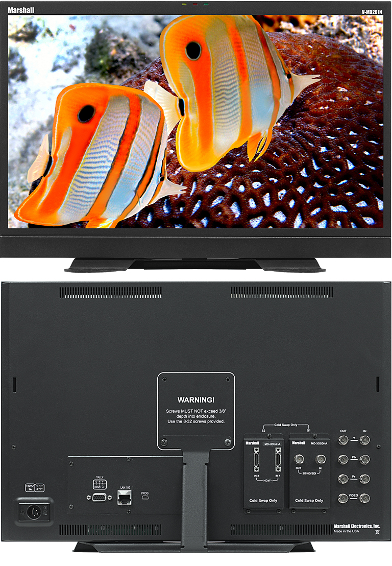
Marshall Electronics proudly announces the latest addition to the MD series of rack mount monitors. The MD series offer a flexible modular solution to system integration. These rack-mountable monitors can be configured with a variety of video inputs that can be ‘swapped’ or interchanged in the field based on your evolving needs and requirements. This eliminates the need to upgrade or replace equipment when a different input or application is required. This ‘future proof’ solution provides flexibility and reassurance when necessary, especially in multi-monitor rack mount units. The V-MD201N is the latest addition to the Marshall line of Modular Design (MD) Monitors. This new 20′ MD now includes the same Network feature found on our other rack mount MD units. The V-MD201N offers 1600 x 900 resolution with excellent viewing angles of 178degrees Up, Down, Left and Right along with a long life white LED backlight unit. The V-MD201N includes Composite and Component loop-through inputs, along with two Modular Input Slots. A variety of Input modules are available including the MD-3GE, 3G/HD/SDI with loop-through, Fiber-Optic input/output modules, and more. Operational features include Status Display, False Color Filter, Markers, Freeze Function, Color Temperature Presets, RGB Gain / Bias Adjust, Pixel-to-Pixel, Blue Gun, Hard Tally, four user-definable function buttons, and more. Marshall’s new MD monitors integrate Telecast Fiber System’s TeleCube Fiber-Optic HD/SDI transmission input/output modules. These new fiber modules deliver the industry’s broadest range of digital rates while maintaining pristine signal quality that broadcasters and integrators demand.
Network Control
Each V-MD series rack includes a LAN port with a built-in web server. This allows the operator to visually monitor and control any or all V-MD series units that are connected to the LAN. Any function that is addressable from the front panel of a V-MD series monitor can be accessed via any Firefox web browser — even on a wireless device.** The rear panel LAN 100 port connects the unit to the LAN. Once connected, the user simply locates the IP address of any one of the units connected to the LAN. This is accomplished by going to the MAIN MENU of any of the connected units and selecting the NETWORK CONFIGURATION submenu. This will then display the IP address of that unit. V-MD units are shipped with the DHCP mode enabled.
Simply type this IP address into the address bar of your browser and the home page for that unit will appear. It is possible to poll your LAN for all other MD units connected by accessing the NETWORK tab from the Top Menu.
The user can then control multiple networked MD monitors at once using a single browser page. The user may select which monitor(s) they wish to control and send commands to those particular monitors. The browser provides real-time status of any connected monitor, ensuring consistent signals / feeds and so forth.
False Color Filter
The False Color filter is used to aid in the setting of camera exposure. As the camera Iris is adjusted, elements of the image will change color based on the luminance or brightness values. This enables proper exposure to be achieved without the use of costly, complicated external test equipment. To best utilize this feature, you must understand the color chart and have a basic understanding of camera exposure. Normally, when shooting subjects like people, it is common practice to set exposure of faces to the equivalent of approximately 56 IRE. The False Color filter will show this area as the color PINK on the monitor. Therefore, as you increase exposure (open the IRIS), your subject will change color as indicated on the chart: PINK, then GREY, then a few shades of YELLOW. Overexposed subjects (above 101 IRE) on the monitor will be shown as RED. In addition, underexposed subjects will show as DEEP-BLUE to DARK-BLUE, with clipped-blacks indicated with a FUCHSIA-like color. Lastly, the color GREEN is used to indicate elements of the image that are approximately 45 IRE. This represents a ‘neutral’ or ‘mid-level’ exposure commonly used for objects (not people).
IMD and Tally
Use the ‘Text Enable’ function to turn the MD Text feature ON. This will cause the ‘Text String’ to appear on the lower portion of the screen. This provides the user with a 16 character on-screen text string. The color, background (opacity), and alignment of text can also be managed by the operator. This same menu allows control of Tally Source. Tally lights (both LED and on-screen) can be enabled/disabled and also set to match ‘Text String’ color.
Optional Input Modules (Type A modules)
MD-3GE – 3G/HD/SDI Input Module with Loop-Through
MD-HDSDIx2 – Two-channel HD-SDI Input Module with switched output
MD-HDIx2 – Two-channel HDMI Input Module MD-DVII – DVI-I Input Module


